The eternal debate among maintenance fitters and design engineers often boils down to a single visual puzzle: does the rubber component sit on the inner diameter or the outer diameter? While many handbooks offer mnemonic tricks, the underlying physical truth is refreshingly simple yet frequently misunderstood. The decisive factor is never the direction of motion, nor the pressure level, but purely the geometric location of the groove's static bottom wall. This article dismantles the positioning logic by tracing the force transmission chain from the gland housing to the dynamic counterface, offering a robust field rule that withstands extreme pressure spikes and temperature variations.
Understanding the Groove‑Bottom Reference
Static Housing vs. Moving Reciprocator
Every hydraulic sealing gland contains two distinct radial boundaries. The first boundary is the moving surface-either the cylinder bore or the piston rod. The second boundary is the stationary bottom wall of the machined groove, which is cut either into the piston body or into the gland housing. This static bottom wall serves as the absolute geometric reference for installing the elastomeric torus. The rubber O‑ring always rests against this motionless floor, regardless of whether that floor faces radially inward toward the centerline or radially outward toward the atmosphere. Recognizing this static reference eliminates the confusion caused by watching the reciprocating part move back and forth.

When a designer specifies a groove, they deliberately allocate a specific squeeze ratio between the O‑ring cross‑section and the gland depth. This squeeze ratio adjustment dictates the initial preload. If the bottom wall sits on the inner circumference-meaning it is closer to the shaft center-the elastomer must push outward. Conversely, if the bottom wall belongs to the outer housing, the elastomer compresses inward. This reciprocal relationship is invariant and forms the bedrock of all dynamic seal calculations.
Piston Seal Configurations and the Inner Bottom Wall
Outward Radial Expansion Against the Cylinder Bore

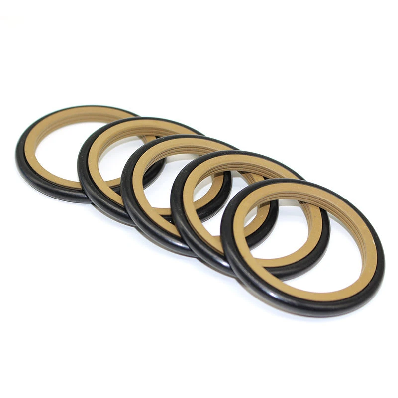
In a typical piston seal assembly, the groove is machined into the outer circumference of the piston head. Consequently, the bottom wall of this groove faces radially outward, but its physical location relative to the system center is inner-it lies inside the piston body. The rubber O‑ring placed into this groove occupies the innermost layer, directly touching the metal bottom. The PTFE slide ring or polyurethane lip rides over the elastomer and contacts the chrome‑plated cylinder barrel.
This configuration demands that the elastomeric energizer converts its compressed strain into a relentless outward force. The force traverses through the PTFE jacket, pressing the sliding element firmly against the bore wall to establish the primary sealing barrier. Without this inward‑located rubber foundation, the sliding ring would lack the initial contact pressure required to seal at low system pressures. Field data indicates that approximately 70% of piston seal failures originate from incorrect O‑ring sizing that alters the intended bottom‑wall squeeze.
Influence of Groove Fill Percentage
The fill percentage of the rubber within the groove cavity directly influences the extrusion gap clearance. If the O‑ring cross‑section is too bulky relative to the groove depth, the friction hysteresis escalates dramatically, generating excessive heat. Conversely, insufficient rubber volume reduces the radial expansion force, allowing the PTFE ring to lose contact with the bore during pressure reversals. Achieving the correct balance hinges on precise measurement of the bottom‑wall diameter, which determines the O‑ring's stretched condition. A stretched O‑ring reduces its cross‑sectional area, a subtle effect that many rebuild shops overlook during routine overhauls.
Rod Seal Configurations and the Outer Bottom Wall
Inward Collapse Mechanism Toward the Piston Rod
Transitioning to the rod seal-commonly installed in the cylinder head or gland cartridge-the groove geometry inverts completely. Here, the machined slot resides on the inner diameter of the housing, surrounding the reciprocating rod. The bottom wall of this groove is located on the outer periphery of the sealing arrangement, farther from the rod centerline. The rubber O‑Ring sits in this outer annulus, while the sealing lip or PTFE ring occupies the inner layer, directly wiping the rod surface.
In this inverted layout, the elastomer must contract radially inward. The compression generated by the gland housing forces the O‑ring to squeeze against the PTFE lip from behind, collapsing the lip onto the rod with a defined hoop stress. This inward collapse mechanism ensures that the rod seal maintains a uniform contact band even when the rod experiences lateral deflection due to load variations. The dynamic response of the elastomer in this outer position is critical for preventing fluid bypass during the retraction stroke.

Backup Ring Synergy with the Outer Groove

When system pressures exceed 300 bar, designers routinely insert a backup ring adjacent to the O‑Ring on the outer bottom wall. The backup ring, typically made of rigid PTFE or PEEK, sits in the groove corner opposite the pressure direction. Its primary function is to prevent the elastomer from extruding into the radial clearance between the rod and the housing. The interplay between the backup ring and the outer groove geometry defines the extrusion gap clearance. If the backup ring is misplaced on the wrong side of the O‑ring, the sealing system undergoes catastrophic failure within the first few pressure cycles. Proper assembly sequence places the backup ring on the low‑pressure side, leveraging the outer bottom wall as a rigid stop.
The Elastomer as a Passive Energizer
Squeeze Ratio Adjustment and Lifespan Extension
The O‑Ring does not actively pump fluid; it acts purely as a passive spring. Its material memory stores mechanical energy during installation and releases it gradually to sustain the contact stress of the primary seal element. The resilience of the elastomer depends heavily on the hardness durometer, typically specified between Shore A 70 and 90 for hydraulic applications. A softer elastomer accommodates greater surface irregularities but suffers from rapid extrusion wear, whereas a harder compound provides superior extrusion resistance at the cost of increased assembly torque interference.
The groove‑bottom force logic dictates that the squeeze ratio must remain constant irrespective of whether the application is a piston or rod configuration. For a given cross‑section size, the gland depth determines the squeeze percentage. Designers often overlook the thermal swell coefficient of the rubber, which alters the effective squeeze at elevated temperatures. When the hydraulic oil reaches 100°C, the O‑ring expands volumetrically, increasing the force against the bottom wall. This thermal effect can either improve sealing or induce destructive friction, depending on whether the initial groove depth accommodated the expansion volume.

Interaction Between Primary Seal and Ant‑Extrusion Ring
The Lateral Support Ring Dynamic
Modern high‑performance hydraulic seals frequently incorporate a lateral support ring alongside the main PTFE jacket. This support ring interfaces directly with the groove sidewall, not the bottom wall. The O‑Ring transmits its axial force into the support ring, which then distributes the load uniformly across the groove flank. This configuration minimizes micro‑motion wear at the interface between the PTFE ring and the metal housing. The presence of the lateral support ring alters the effective stiffness of the sealing system, requiring a recalibration of the bottom‑wall squeeze percentage.

Cyclic Pressure Spike Handling
During rapid valve actuation, hydraulic systems generate cyclic pressure spikes that momentarily double the nominal operating pressure. These transient events induce temporary deformation of the O‑Ring against the groove bottom. The rubber compresses further, storing additional strain energy, and releases it when the pressure normalizes. This dynamic pumping action necessitates a robust bottom‑wall finish-typically Ra 0.8 µm or better-to prevent fretting corrosion beneath the elastomer. Maintaining the specified surface roughness on the groove bottom is as critical as the dimensional accuracy of the groove depth.
Material Swell and Chemical Compatibility
Elastomer Compound Selection for the Bottom Wall

The chemical interaction between the hydraulic fluid and the O‑Ring material directly affects the force transmission across the groove bottom. Nitrile (NBR) exhibits moderate swell in mineral oils, whereas Fluoroelastomer (FKM) demonstrates exceptional resistance to high‑temperature phosphate esters. When the elastomer swells, its cross‑sectional diameter increases, effectively reducing the available gland depth and escalating the squeeze ratio. This phenomenon reverses the original design assumptions, potentially converting a perfectly functioning seal into an overheating liability. Engineers must consult fluid compatibility charts to predict the equilibrium swell state and adjust the groove‑bottom dimensions accordingly.
Breakout Friction Threshold Considerations
The static friction required to initiate movement-known as breakout friction-is heavily influenced by the O‑Ring's grip on the groove bottom. When the elastomer adheres to the metal floor due to prolonged static contact, the initial breakout force spikes significantly. This condition is particularly prevalent in rod seals where the outer bottom wall retains heat. Applying a thin lubricating film to the groove bottom during assembly mitigates this adhesion effect, ensuring smooth activation of the sealing lip during the first stroke.
Common Assembly Errors and Visual Diagnosis
Twist and Shear Damage Prevention
One of the most frequent assembly mistakes involves installing the O‑Ring with an inherent twist, causing uneven contact with the groove bottom. A twisted O‑Ring presents varying cross‑sectional widths around the circumference, leading to localized under‑squeeze and over‑squeeze zones. Visual inspection reveals a helical distortion pattern on the rubber surface after disassembly. Preventing twist requires lubricating the elastomer generously and using a mandrel or pilot tool to guide it straight into the gland channel without rolling.
Misidentifying the Pressure Side
Novice technicians occasionally place the O‑Ring on the incorrect axial side of the groove relative to the pressure source. Remember that the groove‑bottom rule determines the radial position, but the axial placement relative to high‑pressure fluid also matters. The O‑Ring should always reside on the side opposite to the extrusion gap-meaning it must be backed by the groove shoulder that leads into the clearance. This axial orientation, combined with the correct radial positioning, ensures that pressure assists the elastomer in sealing rather than displacing it from the bottom wall.

Simplified Field Diagnosis
The "Bottom‑Wall First" Inspection Routine
When troubleshooting a leaking hydraulic cylinder, disassemble the gland and immediately identify the groove bottom. Check the wear pattern on the rubber surface. If the O‑Ring exhibits flat spots or abrasion marks on its outer diameter, and the seal is a piston type, the configuration is correct-the wear indicates proper outward expansion. However, if a rod seal shows external wear on the O‑Ring's outer diameter, it signals incorrect placement; the rubber should show compression marks on its inner diameter. This rapid visual heuristic saves hours of unnecessary tear‑down analysis.

Pressure Testing for Squeeze Validation
A practical field test involves pressurizing the cylinder to 50 bar and monitoring the leakage rate at the rod end. If leakage exceeds acceptable limits despite a new O‑Ring, the issue likely resides in the groove‑bottom depth rather than the rubber size. Measuring the gland depth with a depth micrometer and comparing it to the O‑Ring cross‑section will confirm whether the squeeze ratio falls within the nominal 10% to 15% range. Rectifying the groove depth through machining, rather than experimenting with oversized O‑Rings, preserves the integrity of the groove‑bottom force logic.