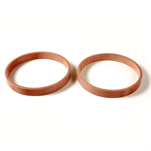
In precision machinery, a simple O Ring often determines whether a system runs leak-free or suffers failure. This toroidal elastomer seal remains a cornerstone of fluid containment. Despite its geometric simplicity, reliable sealing performance hinges on material science, groove design, and installation discipline. This article examines how O Ring behavior under pressure, temperature, and motion directly impacts equipment stability, focusing on details that extend mean time between failures. Even minor installation errors can undermine O-ring seal integrity, making foundational knowledge essential.
The Fundamental Working Principle of an O Ring
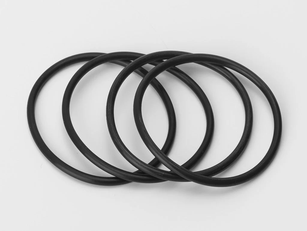
An O Ring seals by deforming inside a gland, creating contact stress. The initial cross-section squeeze provides a static seal; system pressure pushes the ring against the groove's low-pressure side, boosting sealing force proportionally. This self-energizing effect makes the O Ring remarkably efficient.
Squeeze ratio and contact stress distribution
Radial compression between 10% and 25% sets the baseline seal energy. Too little squeeze permits low-pressure leakage; excessive squeeze accelerates stress relaxation and permanent set. Finite element analysis reveals stress peaks near the extrusion gap, helping engineers choose squeeze for specific hardness and gland material.
O Ring Material Selection and Fluid Compatibility
No single compound suits all media. Nitrile handles mineral oils; FKM resists higher heat and aggressive chemicals; EPDM works with phosphate esters but swells in petroleum. Chemical compatibility charts guide choices, but real-world aging involves additive attack, thermal cycling, and oxidation.
Volume swell and compression set interplay
Fluid absorption causes volume swell that can relieve compression, leading to low-pressure weeping. Conversely, heat-driven crosslinking increases compression set, so the ring fails to rebound after load removal. Monitoring hardness shifts in service helps predict O-ring degradation before a visible leak occurs.
O Ring Groove Design and Dimensional Control
The gland cavity defines O Ring behavior. Radial clearance, surface finish, and groove width determine seal life. A common mistake is insufficient fill ratio; the groove must accommodate the swollen ring without exceeding 90% fill to avoid extrusion. For dynamic service, surface roughness balances lubrication retention and wear.
Extrusion gap and backup ring integration
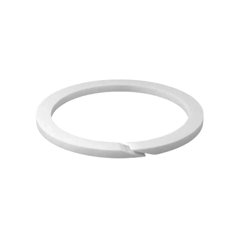
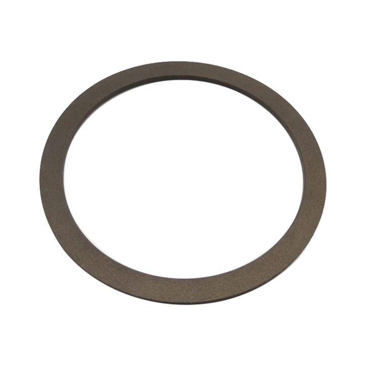
In systems above 5 MPa, the elastomer can extrude into the clearance gap and suffer nibbling damage. Adding a PTFE backup ring bridges the gap and protects the O Ring from explosive decompression. Proper O-ring groove design accounts for thermal expansion differences between metal and polymer, critical in cryogenic or steam applications.
Common O Ring Failure Modes in the Field
Even well-chosen O Rings fail when limits are exceeded. Recognizing failure patterns supports root cause analysis. Spiral failure appears in dynamic reciprocating seals from localized friction twisting the ring. Blistering and explosive decompression occur in high-pressure gas when gases permeate and expand during rapid depressurization.
Nibbling and abrasion signatures
Material loss on the low-pressure side indicates excessive clearance or pressure spikes. A nibbled O-ring surface looks rough and chipped, unlike uniform wear. Fixes include reducing diametral clearance, using harder compounds, or fitting backup rings.
Proper O Ring Assembly Techniques
Many early O Ring failures stem from assembly damage. Cutting, twisting, or overstretching creates stress risers. Lubricating with compatible grease before install prevents dry starts and eases seating. Avoid sharp threads and burrs along the insertion path.
Pilot chamfers and lead-in tapers
A 15–20° chamfer on bores and pistons greatly reduces pinching risk. This allows gradual compression instead of shearing. For blind assemblies, dedicated O Ring tools prevent damage that leads to static seal blowout.
Storage and Shelf Life of O Ring Products
Elastomers degrade in storage from ozone, UV, and heat, causing chain scission. Standards like ISO 2230 specify shelf-life limits by polymer type. Keep O Rings in sealed opaque bags away from fluorescent light and motors to preserve properties.
Visual inspection criteria before use
Before fitting, check each O Ring for cracks, tackiness, or color change. A sticky feel suggests plasticizer loss or early breakdown. Stretching an O-ring seal can expose brittle fracture points. Many sites now use first-in, first-out rotation for static O-ring seal inventories.
O Ring Performance in Dynamic Applications
Dynamic sealing adds challenges. The O Ring must slide while maintaining lubrication. Stiction can cause jerky cylinder motion. Low-friction compounds or PTFE coatings help. Choosing the correct O-ring cross-section for the stroke length further prevents rolling.
Spiral twisting and lubrication regimes
Insufficient fluid film causes high friction that rolls the ring, leading to spiral failure. Surface finish around 0.2–0.4 μm Ra and proper oil viscosity generate hydrodynamic lift. Monitoring rod seal leakage warns of dynamic O Ring wear trends.
Static O Ring Sealing in Extreme Environments
Certain applications need sealing below -50°C or in steam above 200°C. Low temperature reduces elastomer elasticity, risking leaks before warm-up. Silicone and fluorosilicone offer low glass transition. For steam, perfluoroelastomer (FFKM) O Rings deliver thermal stability.
Thermal cycling and joint relaxation
Repeated thermal cycling loosens flanges, gradually reducing O Ring squeeze. Spring-energized PTFE seals sometimes back up standard O Rings in vacuum. Accounting for thermal expansion mismatch between aluminum housings and the O-ring material prevents cryogenic gapping.
O Ring Specification for Subsea and Sour Service
Harsh oilfield conditions demand O Rings resistant to rapid gas decompression and H₂S. NORSOK M-710 qualification tests elastomers for explosive decompression. Optimized cure and carbon black reinforcement reduce internal blistering.
O-ring permeation and blister mitigation
CO₂ and H₂S permeate the matrix under pressure. Controlled decompression lets gas diffuse out without tearing. Specifying O-rings with low permeation and using decompression grooves in the gland preserves seal integrity in subsea connectors. This approach is now standard in deepwater wellhead equipment.
The Next Generation of O Ring Design and Monitoring
Digitalization is reaching seal technology. Sensors embedded in O Ring glands measure compression and temperature in real time, signaling replacement need. Additive manufacturing merges O Ring geometry with backup features in one piece. These shifts turn the O Ring into a predictive maintenance asset.
Self-diagnosing seal systems
Smart O-ring assemblies with micro strain gauges transmit health data to monitoring platforms. Though nascent, this reduces unscheduled downtime and refines O-ring specifications. The O Ring's simple form continues evolving, sustaining its role in dependable machinery.
Ultimately, the O Ring's sealing performance is not just about the polymer loop but the complete system-groove, fluid, motion, and assembly practices. Equipment stability frequently hinges on these subtle interdependencies. By giving proper attention to material selection, dimensional tolerances, and failure analysis, maintenance engineers extend service intervals and avoid unplanned outages. In an era of increasing automation, respecting the physics of this simple seal ensures that critical machinery keeps running. Proper O-ring stewardship is a cost-effective reliability strategy.