

Understanding the Fundamental Purpose of Guide Components
Defining the piston guide ring wear limit measurement

A hydraulic cylinder is only as stable as its weakest lateral support. Guide components exist to absorb the transverse loads that pistons and rods inevitably encounter, preventing metal-to-metal contact between the moving element and the cylinder bore or gland housing. Without proper radial bearing support, even a perfectly machined rod will eventually score the gland and allow catastrophic drift. Field technicians often set a piston guide ring wear limit measurement based on half the original radial thickness; exceeding that threshold means the guide components have lost their ability to centralize the piston and protect the seal. This simple checkpoint, overlooked in many maintenance routines, directly determines whether a cylinder will run another 2,000 hours or fail unpredictably under a side-load spike.
How Guide Components and Guide Wear Rings Work Together
Calculating hydraulic cylinder guide band installation tolerance
A guide wear ring is not merely a spacer. When integrated into the overall guide components assembly, it carries the full radial force and must be sized to leave a precise running clearance. Getting the hydraulic cylinder guide band installation tolerance wrong by as little as 0.05 mm can either seize the piston during thermal expansion or create excessive slop that hammers the rod bearing. The guide wear ring bridges the gap between the hard metal parts and provides a sacrificial, low-friction surface. It also plays a secondary role in centering the seal package so that the lip wipes evenly and the extrusion gap remains symmetrical. In high-boom excavators, pairing a filled-PTFE guide wear ring with a properly toleranced groove in the guide components prevents the chronic heel peeling that plagues rod seals working against unbalanced digging forces.

Material Selection for Guide Components: The Wear Ring Advantage
Composite guide strip material properties for low speed

A standard glass-filled nylon wear ring works beautifully at moderate speeds, but when a cylinder operates in the stick-slip regime of low-speed, high-load movements, composite guide strip material properties become decisive. A resin-bonded fabric wear ring, impregnated with PTFE and graphite, can maintain a coefficient of friction below 0.08 without requiring external lubrication, even during prolonged dwells. This makes it an excellent choice for guide components in steel mill roll-bending cylinders where the piston can stand still under full pressure for hours. On the opposite end, if the hydraulic medium is a biodegradable synthetic ester, a wear ring made of standard acetal may swell; here, the guide components must incorporate a polyester-based strip resistant to hydrolysis. Material selection is always a three-way negotiation between load capacity, chemical compatibility, and the allowable stick-slip threshold.
Precision Machining of Guide Components with Integrated Guide Ring
Avoiding misalignment in guide ring groove machining
A guide ring sits in a groove that must be square to the piston or rod axis. Even a 0.02 mm taper across the land diameter will tilt the guide ring, concentrating the entire side load on one edge and accelerating localized wear. When machining guide components with an integrated guide ring seat, shops rely on mandrel-mounted setups and post-grinding inspection with a dial indicator referencing the piston bearing journals. The groove shoulders need a polished radius, not a sharp corner, because a sharp edge can dig into the softer guide ring material during assembly and start a tear. For repair jobs on large-bore cylinders, some machinists use a portable orbital lathe to re-cut the guide ring groove in situ, bringing the worn guide components back to within 0.03 mm run-out and restoring full bearing surface contact.

The Impact of Guide Components and Guide Strip Design on Friction
Comparing full-round guide strip versus split guide strip

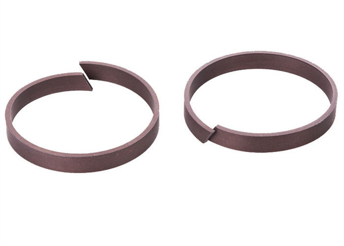
Guide strip geometry has a direct influence on breakaway force. A full-round guide strip offers 360-degree support and the lowest possible unit pressure, ideal for turret rotation cylinders that require micron-level precision. However, in field repair situations where the rod cannot be fully extracted, a split guide strip becomes the only practical option. Modern scarf-cut split guide strips, when correctly installed in the guide components groove with the cut offset from the load zone, perform nearly identically to a continuous ring. The critical factor is ensuring the strip material has enough resilience to close the cut gap at operating temperature, preventing a notch effect on the seal. A cotton-fabric reinforced phenolic guide strip still holds its place in older water-glycol systems where many thermoplastics soften, reminding us that the evolution of guide components never fully discards proven legacy materials.
Hydraulic Cylinder Guide Components: Critical Dimensional Tolerances
Measuring side play with a guide wear ring installed
Side play is the diagnostic language of guide components. After fitting a new guide wear ring onto a piston and sliding the assembly into the bore, the radial movement should be measured with a dial indicator through the port opening. A typical target is 0.1–0.3 mm total indicator movement for a bore under 150 mm. Any reading higher than that suggests either an undersized wear ring or bore wear beyond the allowable hydraulic cylinder guide band installation tolerance. While the rod seal handles dynamic sealing, it is the guide components that dictate whether the seal ever sees an eccentric load. When a cylinder is serviced without checking this side play, a fresh rod seal can fail within 50 hours simply because the piston was running tilted, forcing one lip to carry all the friction and heat.

Installation Practices for Guide Components in Heavy Equipment
Cold fitting techniques for PTFE-based guide components

PTFE-based guide components can be notoriously stiff at room temperature, making them prone to nicking during installation. Warming the guide wear ring or guide strip to approximately 50°C in clean hydraulic oil softens it enough to slip over the piston or into the gland without permanent deformation. Some fit a split guide strip by first coiling it into a helix smaller than the piston diameter, then uncoiling it inside the groove; this eliminates the over-stretching that creates a permanent yield and a loose fit. Another field tip for installation of guide components in log-loader cylinders is to use a thin plastic sleeve over the rod threads and keyways, letting the guide strip slide over a smooth uninterrupted surface. A cut or gouge on the bearing face of a guide ring during mounting will act as a dirt trap and rapidly degrade the entire sealing system.
Troubleshooting Premature Wear of Guide Components
Interpreting guide ring abrasion patterns
Interpreting guide ring abrasion patterns: uniform light scuffing means normal break-in; wavy polished arcs on one side indicate a bent rod; deep circumferential scoring signals embedded contamination. A spiraling open split guide strip often reveals an overly tight hydraulic cylinder guide band installation tolerance.

Maintenance Schedules for Guide Components and Their Service Life
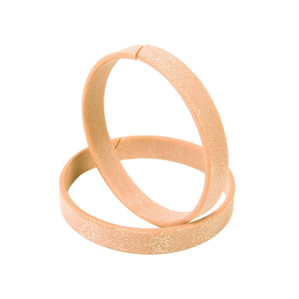
Field experience with forestry forwarders shows that guide components should be inspected no later than every 4,000 operating hours, regardless of whether the cylinder is leaking. Even with ideal filtration, a slow accumulation of hard carbon particles embeds into the soft wear ring surface and transforms it into a lapping tool that quietly grinds the steel bore. During scheduled rebuilds, the piston guide ring wear limit measurement must be taken at three circumferential points; a wear ring that is still within spec on the top measurement but deeply grooved on the bottom indicates a persistent downward side load, perhaps from a misaligned attachment. Replacing only the seals and leaving worn guide components in place is a false economy-it guarantees the new seals will inherit the same eccentric running conditions and fail prematurely.
The Role of Guide Components in Contamination Control
Contamination removal is an unspoken duty of guide components. The guide ring or guide strip acts as the first line of defense by mechanically scraping large particles off the bore wall before they can reach the rod seal lip. Some guide strips are designed with shallow helical grooves that pump debris-laden oil back toward the low-pressure side during the stroke, acting as a rudimentary one-way cleaning element. In extremely dirty applications like cement plant hydraulics, phenol-resin guide strips with embedded brass particles provide a wiper-like scraping action that doubles the life of the primary polyurethane seals. When guide components are undersized and allow a heavy film of contaminated fluid to ride past, the rod seal is forced to do all the particle exclusion work, leading to its rapid disintegration.

Upgrading Legacy Systems with Modern Guide Components

A 1970s-era injection molding press often has a piston running directly against a cast-iron bore, with no dedicated guide components at all. Retrofitting such a cylinder with a modern guide wear ring made from glass-filled PTFE can restore a consistent running clearance without the cost of a re-bore. The trick is to machine the existing piston to accept a thin guide strip, reducing the clearance from the original 0.8 mm down to 0.15 mm. This retrofit not only quiets the hammering sound of metal-on-metal contact but also provides the radial support that contemporary stepped-crown seals require. When upgrading guide components on legacy single-rod cylinders, always verify that the rod end guide bush is equally upgraded; otherwise, the piston end will be perfectly centered while the rod end continues to wallow, creating a bending moment on the rod.
The Cost-Efficiency of High-Performance Guide Components
A premium woven-glass PTFE guide ring may cost three times as much as a standard acetal one, but the economics shift dramatically when downtime is factored in. One unplanned failure of a marine crane luffing cylinder, caused by a disintegrated guide strip that allowed the piston to score the bore, can result in a two-day vessel charter loss far exceeding the cost of an entire set of guide components. In continuous-caster mill applications, where a single hydraulic failure stops production valued at several hundred dollars per minute, the practice of downgrading guide components material to save a few euros per ring has long been abandoned. Lifecycle cost analysis consistently shows that the guide ring is the cheapest insurance policy in a hydraulic system's bill of materials.
Field Inspection Techniques for Guide Components
A quick field inspection of guide components requires no gauge blocks. The technician pushes the rod sideways with moderate force and observes the deflection at the gland; any perceptible metallic clicking indicates the guide wear ring has collapsed. For a more quantitative check without disassembly, a dial indicator on the rod end, combined with a pry bar leverage, reveals the total radial free play. Comparing this value with the factory tolerance for side play with a guide wear ring installed instantly tells whether the guide components are still functional. In telescopic cylinders, a segmented guide strip can sometimes pop out of its groove and fold over during retraction, a condition detectable by a sudden increase in cylinder drag and a rhythmic screech. Caught early, this saves the tube inner wall from deep scoring.

Future Trends in Self-Lubricating Guide Components
Self-contained lubrication is the next frontier for guide components. R&D teams are testing guide rings with micro-reservoirs of solid lubricant that are released incrementally as the bearing surface wears, maintaining a consistent friction coefficient over 15,000 hours without relubrication. Another promising direction is the use of carbon-fiber-reinforced PEEK guide strips that combine the extrusion resistance needed for 700-bar systems with a thermal expansion coefficient nearly matching that of steel, eliminating the cold-clearance compromise that plagues all-plastic guide components in mobile hydraulics. As digital twins become standard for critical cylinders, real-time sensor data from the rod side guide components will be able to predict wear progression and alert the maintenance system weeks before a mechanical contact occurs.
Ensuring Lateral Stability with Correctly Specified Guide Components

Lateral stability is the defining deliverable of guide components, and it is achieved only when the guide ring width-to-diameter ratio, the bearing pressure, and the clearance envelope are all correctly balanced. A short, narrow guide strip on a long-stroke cylinder is a recipe for stick-slip and seal starvation, while an overly wide guide ring on a small-bore piston needlessly increases friction and heat. The final validation always happens in the machine frame, where the guide components prevent any measurable angular misalignment of the rod under full rated load. That quiet, invisible alignment is what allows a deep-draw press to hold a sub-millimeter product tolerance over millions of cycles, and it all starts with a properly sized guide band resting in a clean, square groove.
